Popular Posts

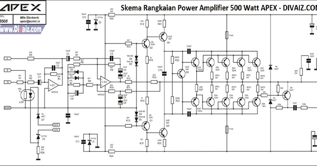
Skema Power Amplifier Built Up Rakitan – Bagi anda yang sudah lama berkecimpung di dunia elektronika pastinya sudah tak asing lagi dengan yang namanya rangkaian amplifier. Bagi anda yang belum tahu, amplifier adalah rangkaian elektronika yang berfungsi untuk menguatkan sinyal.
The stereo signals coming from the line outputs of the car radio amplifier are mixed at the input and, after the Level Control, the signal enters the buffer IC1A and can be phase reversed by means of SW1. This control can be useful to allow the subwoofer to be in phase with the loudspeakers of the existing car radio. Then, a 12dB/octave variable frequency Low Pass filter built around IC1B, Q1 and related components follows, allowing to adjust precisely the low pass frequency from 70 to 150Hz. Q2, R17 and C9 form a simple dc voltage stabilizer for the input and filter circuitry, useful to avoid positive rail interaction from the power amplifier to low level sections.
The transistors are 2SC3858 (NPN) and 2SA1494 (PNP), and feature high bandwidth, excellent safe operating area, high linearity and high gain. Driver transistors are 2SC5200 (NPN) and 2SA1943 (PNP).
Klyuch k igre nensi dryu sekret starinnih chasov. All devices are rated at 230V, with the power transistors having a 150W dissipation and the drivers are 50W. This circuit describes an amplifier, power supply and tests procedures that are all inherently dangerous. Nothing described in this article should even be considered unless you are fully experienced, know exactly what you are doing, and are willing to take full 100% responsibility for what you do. There are aspects of the design that may require analysis, fault-finding and/or modification.
...'>Skema Rangkaian Driver Power Amplifier(19.01.2019)
